Just an FYI - maybe save some of you some time...
I priced out the components for Exercise 34 on both Sparkfun.com and phanderson.com - summaries below. The advancedmicrocircuits.com website didn't seem to have the 3.5mm stereo socket (Figure 5-126) and their search feature just plain stinks... took me a few minutes to find the USB cable but had to search for 'picaxe usb' to locate it...
Total costs, with shipping are:
Sparkfun.com - $40.89 - this price is for 2x of the 08M chip, 1x of the USB cable, and 1x of the stereo socket adapter.
Phanderson.com - $38.35 - your price may differ as they use your zip code to estimate shipping costs... but this order comes with 3x of the 08m chip, 1x of USB cable, and 1x of stereo socket adapter.
I placed my order with phanderson.com today. I probably should have checked mouser.com and others, so if any readers do so, please share your findings - thanks!
Thursday, December 30, 2010
Chapter 5 - Experiment 32 Do Over

Well, I finally managed to grab some time to get back to the circuit on page 277... I bought a smaller breadboard that will allow me to mount to the robot (if I can ever get this thing working) and not have to solder every component... saving me some aggravation if debugging is required.
As you can see from the video, I've made a giant step forward - the motor spins forward until either of the switches is pressed... if the switch is held down, the motor reverses direction and continues reversing until the switch is released. But...
This isn't how it's supposed to work. When the robot hits a wall or table or other obstacle and a microswitch is pressed, the robot is supposed to reverse direction for about 5 seconds (more on that in a minute) and then move forward again... the wheel mounted to the moving pivot is supposed to help the robot find a different (random) direction to move.
Now, a few things that may or may not be affecting this circuit - first, I don't have a 0.01 uF capacitor for C2 in the circuit - I have a 0.1uF ... but I do have a 47uF cap for C1. If I understand the 555 chip correctly (referring back to page 157 for monostable mode) - a 47uF cap is on pin 6... and I've tried the 100K potentiometer at both settings (using a screwdriver to maximize and minimize the resistance) but no change.
I'm going to go back and take another look at my circuit, but I've double checked all of the circuits resistor values and all my wiring of the 555 and the relay. Because the motor is spinning forward UNTIL a microswitch is pressed, I think I'm close to getting this to work... but why it won't spin in reverse for the full 5 seconds still alludes me...
Wednesday, October 20, 2010
Chapter 5 - Exercise 32 Update 5

Per Retrophile's suggested tip involving my relay being wired incorrectly, I changed the wiring and figured out my mistake (thanks Retrophile) - I assumed incorrectly that the relay's pins fit logically to the pin layout in the schematic... they don't. Going to the documentation for this particular relay verifies that Retrophile's pin layout is correct.
The two photos here show the rewired circuit - same circuit but just a slight change in photo angle for you to get a better look.
 So, I've rewired the relay and as you can see in the first video below, the motor spins but the switches are still not causing the motor to stop and reverse. I used my multimeter to verify that I've got the switches wired correctly - the top and bottom pins are Normal Open (using the middle pin and bottom pin is Normal Closed and the multimeter shows a 1 when the button is NOT pressed... 0 when it is pressed). Per the schematic, we want the switches open, so I'm fairly sure I've got that wired correctly. I also replaced the 555 chip with a new one, just in case... but no luck.
So, my next step was to shoot another short video showing me using the logic probe on the 555 chip. My description here may not be 100% on the money, but as I understand the chip and the schematic, pushing a switch causes pin 2 to detect a drop in voltage... and causing pin 3 to allow current to flow (or is it just an increase in voltage - is voltage always present? Something to look into...)
As you can see from the video, putting the logic probe on pin 3 and pushing the power button causes the probe to change in pitch... that should be right. But then when I press any switch, pin 3 should change in voltage and be detected by the probe... but nothing happens. Any thoughts?
Friday, October 8, 2010
New Mouser.com web search tool

I will say that, up to now, I have much preferred to use AllElectronics.com versus Mouser.com - mainly because I've found Mouser to be information overload.
This morning I received an email from Mouser.com about a new web browser add-on for both IE and Firefox called the Mouser Search Accelerator... it'll basically allow you to highlight a component - a word, a part #, name, etc, - and then, without leaving the page you're on, perform a search of Mouser.com. Pretty slick, and I think I'll give it a try soon. Let me know what you think if you give it a spin.
More information on it can be found here - it is something that must be downloaded and installed on your computer, btw.
UPDATE:
 Okay, I installed it on my Firefox (3.6) browser - as you can see, after highlighting an old part # from a previous post, I right click and select to search on Mouser.com - a little fly-out window appears with links to the part and a price... and look at that! The price hasn't changed since I ordered the part back in April 2010.
Thursday, October 7, 2010
Chapter 5 - Exercise 32 Debugging

Suggestions are coming in on ways to test or fix the problems I'm encountering. Let me explain what's happening now.
I've inserted the diode that j suggested... works! The buzzing has disappeared (see video below). So we're getting close. Right now, pushing either switch (that will serve the robot as a trigger to stop and back away from an obstacle) does not stop the motor from spinning - pushing either button is SUPPOSED to cause a drop in voltage on pin 2, so I think my next step is to use a chip tester to see if pin 2 is being triggered. (Right? No?)
 I'm including some pictures here - one is the schematic and the rest are close-up photos of my circuit - maybe I've got an unseen error in my wiring. Be warned - my use of the breadboard is obviously that of a newbie, so I've got wires running all over the place. If I can't figure this out soon, I think I'll start over and try to rewire a bit cleaner and closer to the layout of the schematic.
 Thanks in advance for all your comments and suggestions - I love learning by doing... and making mistakes is another favorite technique of mine as I tend to remember what I did wrong versus what I did right... and that's what drew me to this book in the first place!
First video below is WITHOUT the diode.
Second video is WITH the diode.
(FYI - family visiting this weekend so I may not get much more work done on this circuit until early next week.)
Chapter 5 - Exercise 32 Update 4
A short update today - only a small bit of progress... let me explain.
First off, I've gotten over sharing my dumb mistakes with the world via this blog... when you decide to walk through a book and perform all the tasks/exercises/experiments and share your results, you've gotta expect to have the occasional embarassing moment. I've had plenty during my tour of Make: Electronics, and I'm not done yet...
So, here's what happened - take a look at the schematic for Experiment 32 (if you have the book)... see that 50K trimmer there and how the left side of the resistor isn't connected anywhere? That's not an error... but I thought it was! So, I just connected that end where it felt right.
And... of course... the video yesterday shows my results. So, after Mr. Platt explained this little techy bit to me, I pulled that wire and ran the circuit. The motor still spins, but THIS TIME the two microswitches, when pressed, stop the motor. Progress. But not fixed.
Pressing either of the microswitches is supposed to reverse the motor's spinning for a short period of time. But it doesn't. Instead, pressing a microswitch causes the relay to buzz LOUDLY and the motor does stop rotating... almost. If you hold down the microswitch, the motor appears to stop but in reality it still rotates in the original direction but VERY slowly... almost impossible to see. Oh, and the relay buzzes LOUDLY! Release the microswitch and the motor begins rotating in the original direction again.
So, don't connect the 50k trimmer on both ends... just the one shown in the figure. And if anyone has any ideas WHY my relay is buzzing AND why either microswitch doesn't cause a reversal in the motor spin, please let me know... I'm taking a step back to think about this for a bit.
Wednesday, October 6, 2010
Components Pack 1 Frustrations
I just went over to the Components Pack 1 webpage to confirm the list of components in the kit... and I was surprised to find a large number of negative reviews... after reading over them, it appears that the kit has been out of stock for just over a month (earliest 1 star review was August 21... latest Oct 1).
I'm not sure what's happening, but if you're trying to gather up the parts on your own, I've tried to include my Shopping Lists in previous posts, including part#s and sources. I may have missed a few, but hopefully there's enough information there to help you consolidate some shipping from multiple sources. (Click on the Shopping List label to the right of the screen to filter the blog and display my shopping list articles... if I've missed one, please let me know.)
I know it's frustrating - I was already well into Chapter 4 when these kits became available and it would have been nice to have all these parts together in 2 kits. But hang in there - if you've got the book and are wanting to get into it, keep in mind that the Chapter 1 exercises are low-cost, really... I'm not counting the tools such as the breadboard, soldering iron, etc... I'm talking about the components like LEDs, batteries, a few capacitors, resistors... you can easily get deep into Chapter 1 before spending a lot of money and in that time, maybe Components Pack 1 will become available. (It looks like Pack 2 is still available.)
Chapter 5 - Exercise 32 Update 3

Before cutting out the wood for the shell of the robot, I figured it might be wise to actually wire up the schematic first and see if I can get all the electronics to work. As you can see from the video and picture, I've managed to wire up the motor - I've got a temporary push button that allows me to provide power to the circuit. I'll get an actual on-off switch once I get the circuit de-bugged.
The circuit is definitely providing power (6V) to the motor, but the two microswitches are not working as desired. When one is pressed, it's supposed to drop the voltage on pin 2, triggering the coil and reversing the spin on the motor... but that's not happening. Pressing either switch does not reverse the motor. I'm using different microswitches than the ones seen in the chapter, but I don't think that's the issue.
I also need to get out my chip tester and make sure that voltage is detected on pin 3 that runs to the coil.
Obviously, any suggestions my readers may have will be appreciated.
Monday, September 27, 2010
Chapter 5 - Exercise 32 Update 2

My motor, wheel mount, and other bits arrived today. As with most electronics ordered, there's no paperwork on any of it. I can figure out most of it, but the motor has two unlabeled soldering points... my guess is that it DOES matter which wire goes where as the motor needs to spin in one direction specifically... so... I'll need to revisit the Solarbotics website shortly and see if they have any documentation. Otherwise, The Internets will need to deliver!
I'm going to mark out the cuts tonight for the wood pieces that will make the shell. Not going for accuracy here, so I'll likely just use a handsaw and not flip the old tablesaw on for such small (and thin) plywood.
More to come...
Wednesday, September 22, 2010
Chapter 5 - Exercise 32 Update
My box of parts has shipped from Solarbotics, so it's just a waiting game now for the motor and other bits. I was ready to cut the 1/4" plywood but decided to wait until I get the motor and determine that it can actually be mounted properly, including the hole I'll have to drill for it to drive a wheel.
In the meantime, I took a look ahead to the next robot that will require two photoresistors and two servos. I didn't find what I needed at Solarbotics, so I'm going to keep looking. One thing I'm finding is that servos on a lot of electronics websites come with almost no documentation or so much that you can't make sense of it. For those of you who have not yet started in on Chapter 5, just be warned that there's a fair bit of hunting involved - many of the key parts don't come in either Make: Electronics component kit 1 or 2... makes me think Make might want to consider a final kit titled "Chapter 5: The Missing Bits."
In the meantime, I took a look ahead to the next robot that will require two photoresistors and two servos. I didn't find what I needed at Solarbotics, so I'm going to keep looking. One thing I'm finding is that servos on a lot of electronics websites come with almost no documentation or so much that you can't make sense of it. For those of you who have not yet started in on Chapter 5, just be warned that there's a fair bit of hunting involved - many of the key parts don't come in either Make: Electronics component kit 1 or 2... makes me think Make might want to consider a final kit titled "Chapter 5: The Missing Bits."
Sunday, September 19, 2010
Chapter 5 - Exercise 31 Final


So, it was a very nice afternoon today (a bit hot, though) in Atlanta - sunny sky, no clouds, no rain. I had a 3 year old helper who was very curious about all the wire and odd bits sitting on the deck table. After running some unshielded copper wire almost 80 feet and tying it off with the recommended polyrope to a tree, I wired up the remaining circuit as shown on page 265 in Figure 5-66.
 With high hopes, I inserted my earphone and moved the gator clip down the wrapped bottle, trying each tap.
No luck.
So... I began troubleshooting. First, checked and then double-checked all my gator clip connections. They were good - and every time I clicked on a tap, I'd hear a slight electrical snap in the earphone... kinda like the crackle of static on a radio. Checked each tap again... nothing.
Next I replaced the Germanium diode... I purchased a bunch so I swapped it out two more times, checking the taps. No luck, other than the crackle in the earphone again.
At one point... maybe it was wishful thinking... I honestly think I heard something. Very faint... there just for a second and then gone. I played with various taps and checked all my connections again, but just had no luck picking up anything.
Still... I had fun. And I understand the theory and what SHOULD have happened and WHY. I wish I'd had luck, but I honestly don't even know where the nearest AM broadcast is coming from... living in Atlanta, I've just assumed I'd pick up something!
If any readers perform Exercise 31 and have luck, PLEASE let me know! I'd love to be able to share some pictures or video or even a recording of any transmission you hear with your project.
Up next... I'm going to cut up the parts this week for the robot in Exercise 32... today I managed to swing into the local hardware store and picked up the following:
1 piece of 2x4 1/4" Sandiply (sanded really smooth on both sides) $7.98
1 package of 2" utility hinges (3 per package) - $2.21
1 package 3" diameter felt circles (for under the feet of furniture) - $3.78
 Yeah, I know... felt circles? Well, they're 3" in diameter with no center hole drilled and they are very stiff and 1/4" thick. Perfect for the wheels (and, hey... they won't scratch my floor! Bonus!)
Saturday, September 18, 2010
Update and Exp32 Shopping List (Partial)
I'm hoping for some good weather tomorrow (weather.com says YES) so I can head outside and put the finishing touches on Exercise 31... try out my little radio and see if I can pick up any of the AM band radio stations around Atlanta. I hope so... would be a nice surprise.
In preparation for the upcoming Experiment 32 - you know the one if you've been looking ahead in the book like I did! - building the Little Robot Cart. After placing a few phone calls to a few places in Atlanta, I basically decided that with the $6.00 shipping that solarbotics.com charges, I'll end up saving some money if I just wait a week or so for the following components:
1. DC Gear motor
2. Disc for motor
3. Two SPDT microswitches
4. 1 DPDT nonlatching relay
In the meantime, tomorrow I'll also be heading up to my hardware store to buy some 1/4" hobby plywood. Yes, I know... the author recommends ABS plastic. But right now I'm not wanting to invest in a plastic bender and I'm comfortable working with wood and have the right tools to cut the proper pieces (see on page 275). Not sure about the wheels, but I'm fairly certain I can find some thin wood wheels at a Michael's or Hobby Lobby that will fit the bill. Otherwise, I'll invest in a 3" bore hole bit and cut my own. I may attach everything with screws or I may go ugly and just stick everything together with superglue or Gorilla glue... not really going for something to enter in a science fair, so not concerned about looks.
If anyone finds these components elsewhere (and cheaper), please share with your fellow readers... in the meantime, I'm posting a screen capture here of the part #s and prices (and quantities) for Solarbotics.com.
Kinda glad to have found some time to get back to the book - I apologize to my readers for such a lengthy delay in finishing up the exercises. Now let's finish this book!
In preparation for the upcoming Experiment 32 - you know the one if you've been looking ahead in the book like I did! - building the Little Robot Cart. After placing a few phone calls to a few places in Atlanta, I basically decided that with the $6.00 shipping that solarbotics.com charges, I'll end up saving some money if I just wait a week or so for the following components:
1. DC Gear motor
2. Disc for motor
3. Two SPDT microswitches
4. 1 DPDT nonlatching relay
In the meantime, tomorrow I'll also be heading up to my hardware store to buy some 1/4" hobby plywood. Yes, I know... the author recommends ABS plastic. But right now I'm not wanting to invest in a plastic bender and I'm comfortable working with wood and have the right tools to cut the proper pieces (see on page 275). Not sure about the wheels, but I'm fairly certain I can find some thin wood wheels at a Michael's or Hobby Lobby that will fit the bill. Otherwise, I'll invest in a 3" bore hole bit and cut my own. I may attach everything with screws or I may go ugly and just stick everything together with superglue or Gorilla glue... not really going for something to enter in a science fair, so not concerned about looks.
If anyone finds these components elsewhere (and cheaper), please share with your fellow readers... in the meantime, I'm posting a screen capture here of the part #s and prices (and quantities) for Solarbotics.com.

Kinda glad to have found some time to get back to the book - I apologize to my readers for such a lengthy delay in finishing up the exercises. Now let's finish this book!
Wednesday, August 11, 2010
One Day Digital Book Sale
O'Reilly has a great deal right now on some eBooks - for $9.99 you can get any of their Top 10 books and guess which book is on that list?
That's right - Make: Electronics is available in digital format for only $10 (no shipping costs!) - if you've been considering purchasing a digital copy or know someone who's shown an interest in the book, this is a good price.
I have the digital version on my iPad... I wish I could say that I've been referencing it a lot lately, but a certain 2 month old baby boy has been stealing MUCH of my attention. I keep promising to return and get back to work on the book and I am going to do my best to get back to it this week as I've got some downtime that's finally rolled around.
Anyway - this is a ONE DAY deal, so strike now: http://oreilly.com/store/ddbst.html
Thursday, June 24, 2010
Update on Blog
Sorry, all, for the big delays in posting. My wife delivered a 10lb, 7oz baby boy on June 14th... and the weeks before were a bit crazy as well as the last week and a half.
Baby and momma are fine, life is somewhat returning to normal, and I'm ready to get back to the blog and finish my coverage of the experiments in the book.
I'll try to have a conclusion/summary of Experiment 31 before Saturday... and I've been collecting my notes on Experiment 32 which appears to be one of the larger and more time-consuming exercises. I've been looking forward to that experiment ever since I first skimmed the book, so it's nice to have reached that point... now if I can just find some spare time to cut out the pieces.
Excuses, excuses... thanks for your patience, and I'll get back to work on the blog and book shortly.
Wednesday, June 2, 2010
Chapter 5 - Exercise 31

So we're going to build an AM radio with an empty bottle, lots of wire, a germanium diode, and a cheap earphone... sounds fun.
A few things - I didn't have a 3" diameter bottle, but a 2.5" Flinstone's Vitamins bottle, generously donated by my 3 year old son who allowed me to put the remaining vitamins in ziploc bag. Thanks, D!
After removing the label and cleaning the bottle, I drilled the holes as instructed.
 It's hard to tell from Figure 5-60 how tall that bottle is but I don't think my bottle is tall enough to hold the 12 "taps" that the instructions say to build... and because the bottle's diameter is less than 3", I multiplied by the 16 to get a 40" distance between taps. Doing a little math, I quickly figured out that 12 taps wasn't going to wrap around once I got started...
 BTW, start at the bottom of the bottle and work your way up - it's easier to tie off the wire when you're done wrapping if the holes near the top are exposed - I managed to get my fingers through the bottle opening and get it tied off. The author recommends 22 gauge wire, solid core... I used insulated and I'm glad I did... makes it much easier to wrap and you'll save your fingers from wire-burn... yes, I made that term up, but exposed wire does get hot to your fingers when you're wrapping... your call.
 After wrapping my bottle tightly, I managed to get 10 taps before running out of room... I don't think this will be an issue but may give me fewer chances of success when it comes to picking up a signal. As you can see, my taps aren't spaced as far apart as the author's are in Figure 5-64... crossing my fingers and hoping.
Up next, getting the antennae setup... I've got the germanium diode and earphone, so I need to get some rope that won't interfere with the antenane and keep it from grounding... more to come.
Thursday, May 27, 2010
Special Project

To quote Chris Knight - "It's yet another in a long series of diversions in an attempt to avoid responsibility."
Rather than pull my hair out (because I kinda like having it) I'm taking a very short break from the book to try my hand at an electronics project that is easy to follow and understand from what I've learned from Make: Electronics... here's the story:
My 3 year old son has discovered... MONSTERS! We've tried to assure him they're not under the bed or in the closet, but he has these moments where he's certain they're around the corner... we've tried to assure them there's no such thing... but he's 3! He probably DOES see them with that imagination of his... so...
I've decided to empower him. No longer will monsters be allowed in our house! As long as he has his trusty Monster-B-Gone with him, all is well.
 The Monster-B-Gone is my simple little project involving 6 LEDs moving like the traditional cylon or KITT the super car. Back and forth... back and forth. With the push of a button, my son can banish monsters because, as we all know... monsters HATE the color green! One push of the button and they're off and running! I've already started talking to him about the hows and whys of the animosity between monsters and the color green. I think he's buying it... this should work for a bit and give me time to work on the next solution.
I've based my circuit on the Cylon Pumpkin... if you want to build the same circuit, I've consolidated the author's circuit drawings into a single PDF file you can download here. As you can see from the video, it works fine. I'll be transferring everything to a small project box with a momentary button on the top or side so the batteries aren't being constantly drained. More later as I get the soldering moving forward...
I promise I'm NOT done with the book or the projects... just need to think about something other than Experiment 29 for now...
Monday, May 24, 2010
Chapter 5 - Exercise 29 Update
Well, I don't know... I've tried quite a few things. First, I replaced the wire to the speaker with a high gauge wire (thinner and twisted, not solid core) because I was worried maybe not enough power was being generated. No luck. I also replaced the TEA chip and a few capacitors (didn't have enough of each size to replace them all) but that doesn't seem to have helped either.
Next, I took a look at the adapter. I thought - okay, maybe the adapter just isn't functioning... but no, it works. I used it with some patch cords to connect to a small radio with the right plugs and my iPod played music just fine. So something is wrong with my circuit.
Based on past experiences with this book's exercises, I knew it had to be operator error. Something small and simple to overlook... but I checked all my resistor values, checked where every wire was going (positive or negative voltage), double and triple checked ever TEA chip pin to make sure they were all wired properly and none were ignored... and I'm getting zip.
Is it possible that the iPod via the adapter via the breadboard just cannot power this 8" speaker? Suggestions welcome, but I'm probably going to go ahead and ship to exercise 31 and leave this one alone... I don't have to take it apart for exercise 31, so I'll give it a break and see if a light appears in the sky with the answer.
Argh.
Wednesday, May 19, 2010
Chapter 5 - Exercise 29 part 3

Okay, I'm still having trouble with experiment 29. I'm including some close-up photos here, hoping that someone may catch an error or see something that I'm not doing properly.
 A few things - the schematic on page 251 (Figure 5-41) shows the hookup wire and the 10 microfarad components wired up in series but with a set of pushbuttons used to isolate them. I thought this might be the issue early on so you'll see that I've only got the hookup wire in the circuit... I figure if I can get the sound working with the hookup wire, then I'll pull it out and insert the capacitor.
  Other than that, I believe I've wired up the circuit as seen in Fig 5-41. I've verified all my capacitors and resistors for their values... the TEA2025B chip is inserted with the proper orientation... and I've got the 100 microfarad smoothing capacitor between the voltage inputs. The headphone jack is the only other questionable issue that I'm not sure how to test... I taped the wire inserted into the one socket as well as the one connected to the outer metal surface of the other socket...
One question, though - I used solid core 22 gauge wire for the speaker. I'm wondering if that wire is too "heavy" for this experiment.
Any advice is welcome... I'm not wanting to get bogged down on this experiment but experiment 30 builds on it... so if I can't get it working soon, I'll have to skip 30 and jump to experiment 31. If anyone has successfully completed this experiment with solid results, please let me know, as well. If I can't get it working, I'd at least like to get a video of an actual working project.
Friday, May 14, 2010
Chapter 5 - Exercise 29 part 2

I got everything hooked up and I double-checked the schematic for all the resistors, capacitors, and pins on the chip. I chose to use my iPod with the $5.99 adapter I purchased from Radio Shack.
 I also got the speaker built - it's ugly as it can be but it's bolted to the plastic box and yes... those are Mickey Mouse diapers in the bottom. We use what we can... my son is in pull-ups now, so I don't think he'll mind.
I decided to video the first power up... you can see that below.
Thursday, May 13, 2010
Chapter 5 - Exercise 29
 Apologies for delays in posting recently - throw in a small bit of procrastination with my mistakes in ordering incorrect components and ... you get the picture.
I got most of the schematic on page 251 wired up - it's a variety of colors, isn't it? I do believe there are a couple of mistakes here, but I'm not going to post them to the errata page until I get confirmation from a reader or from the author.
On page 251, for example, the 100microfarad smoothing capacitor for the 9V has the symbol of a nonpolarized capacitor, but the text says to use a regular electrolytic. I'm going with the text because of the author's explanation for WHY to use that type of capacitor...
Also, the 0.15microfarad capacitors are shown as NP type but not labeled as such... here, I'm going with the NP variety (that's all I have anyway) because of the symbol. Also, please note that that 0.15microfarad capacitors are not specified in the shopping list... I don't have any from previous experiments in the book, so I had to grab some of these locally.
 I shot the photographs here before writing this up, so I also just noticed a mistake I made - the NP capacitor sharing the top part of the circuit with the coil is a 10 microfarad, not 100 as I've put in my circuit... fortunately, I haven't powered mine up yet... more on that in a moment.
I'm also wanting confirmation on something in the schematic - the 100microf coming out of pin 6 goes into pin 1... not connected to negative voltage as the other two 100 microf on pins 8 and 11. These are HUGE capacitors, and I'm very nervous about powering up this thing until I get that resolved as well... my initial thought was that that capacitor on pin 6 should at least have a connection to negative voltage, but maybe pin 1 is initially negative (a sink?)... again, not sure so I'm not powering up this bad boy just yet...
I've also got to pick up a headphone socket like the one in Figure 5-42 as well as some hardware to mount my 5" speaker to the plastic box. Will do that today.
We hear so much about audio and video equipment and the high voltages and currents they use/produce... so I hope you can understand my nervousness about plugging this breadboard in until I have all of these details ironed out... don't want a burned breadboard or any exploding capacitors in my vicinity... even with eyeshields on.
Monday, May 10, 2010
Experiments 29 and 30
Experiment 30 builds on Experiment 29 - unfortunately, I've had some bad luck getting the proper components for these 2 exercises. Exp 29 calls for 100 microfarad capacitors of the nonpolarized electrolytic type... ditto for 47 microfarad. I thought I'd ordered the proper BP type capacitors... apparently not.
One thing I did notice about Experiment 29 was that it calls for two 47 microfarad capacitors but they're not seen in the actual schematic on page 251. I do see in the schematic two 0.15 microfarad capacitors... I don't have those either... added to the shopping list. You'll also see a 10 microfarad NP capacitor that's not listed in the experiment's shopping list... argh.
I've called ACK supply and I believe I can get the right components this week, but I'm not driving to that part of town until Wednesday... so Exp 29 and 30 are on hold temporarily. (In the meantime, I've read over Experiment 31 and believe I can go ahead with that one while trying to get the capacitors.)
I'll also need to pick up the headphone socket seen in Figure 5-42 - this isn't on the shopping list either. Thankfully, I purchased one of those big bags of resistors so I've got those covered, including the TEA2025B chip required. Again, sorry for delays, but I'll get back to these two experiments soon.
On to Experiment 31...
Friday, April 30, 2010
Chapter 5 - Shopping List Update
 Got a few more items in for Chapter 5 from various sources.
 First, I purchased 10 germanium diodes and a single piezoelectric earphone from SciToys as the author recommended. Since I was paying for shipping, I ordered 10 diodes instead of just 1... I may never use them but they're not that expensive and I know a few people (including my dad) who are working through the book and I may part with a couple.
I couldn't believe I couldn't find these items locally - no Radio Shack that I called carried either the germanium diodes or the earphone and the few electronics shops I called carried the earphone but it was $10.00 and no germanium diodes.
Note: These items are NOT included in the Components Pack 2 - as a matter of fact, I'm finding quite a few things in the final experiments in Chapter 5 that are not included with Pack 2. (This isn't an error - Pack 2 states it is specifically for Chapters 3 and 4.) I'm trying to capture all the specialty items required for Chapter 5 and will see about making one final Chapter 5 shopping list that contains those items NOT found in Pack 1 or Pack 2. For example, Experiment 28 recommends a 4700 microfarad capacitor but the shopping list specifies 2000 microfarad minimum... if you're like me, you probably don't have any of these in your possession. Again, I'll try and go through Chapter 5 when done and pull together a complete list of specialty items.
 Also, I picked up a plastic box for $1.50 at The Container Store... I was in the neighborhood and remembered that I needed one for Experiment 29.
From SciToys (www.scitoys.com)
10DIODES $7.86
EARPHONE $6.84
(Those are the actual part numbers above with the prices.)
Chapter 5 - Exercise 28
 I'd never seen this application of a coil, but the theory you'll read about for Experiment 28 makes sense.
In the first part of the exercise, I simply wired up the circuit on page 247 and pressed the button. As expected, a single LED lit up on the button press and the other LED lit up on release of the button. It happens quickly. The author recommends against holding down the button because the resistor will get hot fast. You can see this in action in the first video.
The second part of the exercise involves hooking up a capacitor in place of the 220 ohm resistor (don't forget to add in the single 1K resistor). The author states that capacitance works the opposite of self-inductance, so you would think that based on the first exercise, we should see the 2nd LED (on the right in the video) light up first, and then the 1st LED (on the left) after the button is released. The second video shows my results.
 What happened? As I understand it, capacitance resists at first and wants to take most of the current to charge up - so the first LED does light up, but not as bright. Releasing the button causes the capacitor to discharge and I can only guess that the resistance in the coil is very low (compared to LED 1) so the current flows through the coil and then through LED 2. Of course, I could be completely wrong as I expected LED 2 to light up first... then LED 1. Goes to show that electronics don't always behave in the ways we expect them to... (or maybe I wired up this modification incorrectly - if anyone knows, please let me know so I can try again.)
A fun experiment... just be sure to wire up that capacitor correctly (for polarity).

Finally, I got my copy of 'Practical Electronics for Inventors' by Paul Scherz. A quick scan of the entire book and a read of the first few pages tells me that although the material is quite dry (compared to Make: Electronics), it should be very useful. I can already tell that this book should be easier to read and understand after having completed Make: Electronics.
Wednesday, April 28, 2010
ePub digital edition - Update

Thanks go to Seth over at O'Reilly Media, Inc for emailing me an updated version of the book - as you can see, the cover looks great on my iBook shelf.
Monday, April 26, 2010
Chapter 5 - Exercise 27
 Exercise 27 calls for you to destroy a small 2" speaker... the way these speakers are designed, I don't think you'll be repairing it after you've made the required cuts to tear it apart and see how it works. I've taken video of the process if you'd rather not destroy your own speaker.
 The coil of wire wrapped around the small cardboard tube is surprising. It's very fine and wrapped nice and tight, obviously by a machine. If I understand my reading of Exercise 27, the electric current sent to the speaker will create a magnetic field in the coil that will fluctuate... these fluctuations will cause the magnet to move up and down, with the air waves created moving the black paper cover that I cut away from the speaker. The paper cover's movement is what creates the sound waves that the listener hears.
 A very simple device... only two moving parts as far as I can tell - the magnet and the paper cover. Amazing.
Friday, April 23, 2010
Chapter 5 - Exercise 26
 This was another fun little exercise that I've seen in various forms over the years... the picture on page 241 (Figure 5-22) really does hammer the concept home - given the right components, you could create something to generate a sufficient amount of voltage to power a lightbulb or other low power device. Of course, I'm not sure where you'd find a magnet of sufficient size to make this experiment bigger (or safer) but the theory does make sense.
A few notes...
 I wish I'd purchased a slightly wider diameter magnet than 3/4" - the hole in the center of my magnet wire spool is a little over 1" in diameter... a 1"diameter magnet would have been perfect. The 3/4" I had worked, but it bumped the spool and wasn't as easy to move up and down as a magnet that was a tighter fit.
 Also, don't forget to sand off the ends of the magnet wire - I forgot about the little bit of clear insulation over the wires and didn't get any results at first. You can see in the first video that I eventually do get the red LED to light up. (FYI: I connected another LED in the string and got both to light up at about half the number of blinks as a single LED... adding a third LED resulted in zero light.)
 Next, I connected the 100microfarad capacitor as seen in Figure 5-23, with the diode properly oriented. The second video shows that I got up around 2.6 volts... a nice number! I didn't get close to the 10V the author mentions, but there are so many factors at play here that I'm sure I could have reached it with the right diameter magnet and spool hole.
 As the author advises, be careful with these magnets. Fortunately my titanium ring that I forgot to take off wasn't attracted to the magnet. Of course, I didn't keep the extra LEDs and gator clips far enough away and was always having to pull them off. I finally got smart and started storing the magnet in a small plastic container by itself until needed.
Make: Electronics - ePub version
 My printed copy of the book is getting... worn. While sharing it last week with folks at WorldFest, it got handled by kids, adults, and adults who acted like kids. Most of the damage to the book is mine, especially the writing and highlighting in the chapters, but the book is definitely showing wear and tear...
 I've been wanting to get a digital copy for my iPad... and what do you know? O'Reilly is offering a special on eBooks (up to April 30) where you buy 1, get 1 free. Buy 2... get 2 free, etc. One thing I like about their offer is that for most of their books they offer them in multiple formats - PDF, ePub, and Kindle. And another nice point is that they don't have DRM... no annoying password to type in every time you want to read your book. So, I purchased the digital version (ePub) of Make: Electronics and imported it into my iPad. (My free 2nd selection was Head First Statistics - same price, so it was like getting both eBooks half off - I like the topic of statistics and wish I was better at it... this book impressed me in printed form, so there you go...)
 Here are some screen grabs from the iPad. I can shrink or enlarge the text as needed, so the page count doesn't match the printed book since I've enlarged the print just a bit. All in all, it's quite nice thumbing through the pages of the digital version. My only complaint? Take a look at the iBook shelf and you'll see that the cover of the book simply says "Make" and has the author's name. Come on, O'Reilly! How hard will it be to modify the ePub file to display the actual cover of the book? Look - my Apress book "LEGO MINDSTORMS NXT: The Mayan Adventure" has its cover... it just looks so much better (my publisher sent me a copy to see how the ePub conversion worked and looked on the iPad - this author is VERY happy with the results). Maybe someone will fix that.
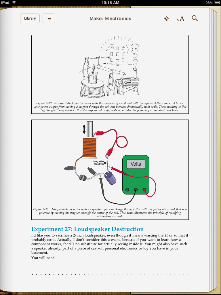 Another nice thing I want to add - by purchasing the digital versions, I get free updates if the books are updated/revised... that'll be nice when the errors found in the book are fixed in a future revision.
Thursday, April 22, 2010
Chapter 5 - Exercise 25
 As the author says, this is an experiment I've seen done numerous times in the past... but never done myself. I remember my high school physics instructor doing something like this but with much more wire... still, 6' of wire did have an effect.
Also, the author points out that stranded wire doesn't give you the same results as solid core... I used some duct tape to secure my coils as I built each level and then wrapped the entire thing in a blanket of tape as you can see in the pictures and video.
 The magnetism wasn't strong, but it was there... and noticeable. While doing this, I had a strange recall of something else I learned way back when... if you take your right hand and make the hitchhiking gesture, notice the direction of your thumb and the direction of the curl of your fingers... if the current is flowing in the direction the thumb is pointing, the magnetic field curves in the direction of the fingers. I'm trying to get my mind around how this can help me with this experiment... maybe it's not relevant. Who knows...?
 So, Experiment 25 - fast and easy. Just give yourself some time to wind that wire... and trust me, holding a 1.5v battery to the ends of the wire won't shock you... but it heats up FAST! I wore a glove the second time around... I could have used alligator clips, but this was more fun...
Sorry for the lack of sound - got a new camera and for some reason I couldn't get the sound to work when I downloaded it to my video editing software - definitely need to read that manual!
UPDATE: Figured out my issue with my new camera - sound is working now on the video below.
Subscribe to:
Posts (Atom)