Sunday, January 31, 2010

Contest Winners - and a New Contest


Back on January 13th, I created a small contest asking readers to help me understand better the circuit seen in Figure 2-60 on page 59. I was having difficulty understanding how the circuit was working... mainly because my limited training in electronics was always about closing a circuit. I could NOT, for the life of me, see how the circuit was closed in Figure 2-60. With the pushbutton open, I saw no closed loop.

But the circuit in Figure 2-60 isn't drawn like a typical circuit. The positive and negative voltage terminals are not drawn together. That's what took me a bit to see... and once I did, I saw the loop. See, in most circuits I'd seen or drawn, the battery (or power) was always drawn with the same symbol... current came out one end and went back in the other... there's your loop.

But with 2-60, the closed loop is there... it's just not drawn that way. You can, for all practical purposes, consider the small black dot just to the right of the big red + sign and the other black dot to the left of the big - sign as touching... if you do that, the circuit is closed.

Okay, enough of that... to the winners. Well, I only had two submissions... so this is an easy one. Both Brian and Nick will each get a Maker's Notebook.

Brian and Nick: I need you to email me at jktechwriter *at* gmail dot com with your mailing addresses... in order to confirm you are who you say you are, I'll email you instructions for confirming you were the person who posted the item. I wouldn't want to send a book to another Brian or Nick!

And now another contest - for this one, I'll be picking two winners - each will receive a Maker's Notebook. This contest is about helping out Charles Platt, author of the Make: Electronics book, and MakerSHED. Here's all that you need to do:

1. Add a comment to THIS post - January 31, 2010 "Contest Winners - and a New Contest."
2. Your comment should be between 50 and 100 words.
3. Let Charles and/or MakerSHED know your thoughts on the book - tell them what you like, what you dislike, or what other books/projects you'd like to see from MakerSHED.

That's it - I'll pick two winners randomly on Feb 13, 2010 so I can award two Maker's Notebooks on Valentine's Day. I'll number all the comments, write down each number on a paper chit, and have my wife pull two numbers randomly from a hat. Two minutes of your time for a chance to win a $20 Maker's Notebook. USA residents only, please.

Chapter 3 - Exercise 14 Part 1

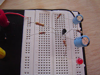
I'm breaking the post for Exercise 14 into two posts. For this first part, I've breadboarded the circuits found on page 118 (Figures 3-75 and 3-76). I initially tried to substitute the 220 microfarad capacitor for C1 because I didn't have a 100 microfarad capacitor... the LED just stayed lit... no blinking. So, yesterday while I was out running errands, I swung in and picked up a few things from Radio Shack. More on that later.

This is the first time we're given a schematic without a matching breadboard drawing - I tried to build the circuit without glancing back to page 85 for help... my first attempt worked, but even with the proper 100 microfarad capacitor, the LED stayed lit... so I knew something was wrong. After checking my circuit again, I found I'd made a few connections wrong with the 2N6027. A quick glance back to page 85 also helped me make sure I'd wired it up correctly. I highly encourage you to try and wire it up without looking at page 85... but if you get stuck, the photo to the left is a closeup of my circuit that works.

After testing that circuit, I moved on to Figure 3-76 and added in C2 and the 330 ohm resistor. I got it correct on the first try... again, try to do this yourself... but if you get stuck, my photo shows a closeup of the breadboard layout that I used successfully.

I'm including two videos here - the first shows the single C1 circuit... the second shows the circuit with C1 and C2. The red LED pulses nicely. After reading ahead in Exercise 14, I found the author is suggesting mounting the LED in some acrylic to make it all look pretty. I think I'm going to try something different... let me explain.


I switched the voltage from 9V to 6V because I found two small watch battery holders (solderable) at Radio Shack for $0.99 each... I also purchased a small project box and a perf board that can be broken in half - one half will fit nicely in the box after I trim the edges a bit. Doing this will also require that I rearrange the layout of the components found in Figure 3-79. I'm okay with that, and I think Mr. Platt would be, too. We're supposed to be experimenting and trying new things, right? I'm including a photo here of the parts - and I'll also provide a parts list and pricing below. No guarantee it'll work, but it should be fun to try.

Up next, I'm going to start the soldering... as you can see, my soldering will differ a bit from Figure 3-79 but I'll try and do my best to photo and explain my layout in the next post.

Coin battery holder CR2032 - Part 270-009 $0.99 each
220 microfarad - Part 272-1029 $1.29
100 microfarad - Part 272-1028 $1.29
PC Board - Part 276-150 $1.99
Project Box Small - Part 270-1801 $2.29

I hope everyone had a great weekend!


Friday, January 29, 2010

Chapter 3 - Exercise 13


For this experiment, I used a green LED and a yellow LED. The green one got the 15W treatment followed by 30W. The yellow got 30W but I added in the small copper alligator clip.

As the chapter states, the 15W was a piece of cake - the green LED was still lit well after 2 minutes of holding the iron to it. I even moved the iron's tip very close to the plastic of the LED but it had no negative effect.

Then I switched over the pencil iron to 30W... and held the tip to the wire. After 40 seconds I was a little worried that maybe I'd selected the Super-LED... or that my pencil iron was defective. But near 1m 30sec, the green LED gave its last performance.

So, I threw away the green LED and replaced it with the yellow... plus I added the little copper clip as seen in one of the photos. I held the 30W iron to it for over 2 minutes, but it just kept on shining.

It's always fun to smoke electronic components - we were promised that in the book's sales sheet, right? The green LED sacrificed itself and I will never forget the lesson it taught me - too much heat can be a bad thing. Use the copper clips whenever possible.

RIP Green LED. You will not be forgotten.

Wednesday, January 27, 2010

Chapter 3 - Exercise 12


Finally... soldering! Something that can be dangerous - yeah! (Just kidding - I was wearing my eyeshields like a pro and all about safety.)

So, we get to solder some wires. I've actually done soldering in the past, but it's been a while, so this was a nice way to ease back into it. As you can see from my photos, I dutifully soldered two wires cross-wise... then two more parallel to one another. My joints were perfect if I might add...

I broke down and went and purchased a 15/30 switchable pencil iron... works very well. It's not super heavy but doesn't feel like I'm at risk of shock or burning myself from mishandling. It's also not that fancy, but at this poing I'm not wanting to drop loads of cash on a fancy soldering machine until I get a little more training... then I'll likely donate one or both of my used ones to a high school.

My final task for this exercise was to solder some solid core wire onto the frayed ends of my AC adapter... as you can see from one of the photos, screwing the braided ends into my breaboard really tore them up... so I snipped a red wire and black wire, stripped the ends, and soldered them to the frayed ends of the adapter. I don't have a heat gun (yet) so I went the cheapy route and used my gas grille lighter. I know... I know... not a good way to do it, but I kept the flame away from the wire, away from the tubing, and did quick little waves over the flame. I plugged in the adapter and checked all the voltages I was receiving to make sure I had a good solder joint on both wires. As you can see from my photo, the multimeter probe clips really came in handy here... allowing me to take the photo without juggling one or two probes and trying to hold them to the wires. A good purchase there...

I didn't have a spare power cord available to do the last exercise (shortening a cord)... and I'm hesitant to actually do it... if anyone does do it and takes a few photos, please email me and let me see if I can grab a few of my readers' photos as examples.

Tomorrow... ruining more LEDs. Glad I bought more than 3 or 4...

Dremel

I mentioned in the previous post that I own a Dremel... if you've been considering purchasing one, check this out... a factory reconditioned one for less than 1/2 the full price - this deal is only for today and, at the time I post this, will last for 16 hours, 35 minutes... and counting.

I've purchased MANY tools from Tooliday.com and can vouch for their service... fast delivery, too.

http://tooliday.com/

Tuesday, January 26, 2010

Chapter 3 - Shopping List

We're up to Chapter 3! If you've looked over pages 95 to 104, you're likely overwhelmed at the stuff you need to gather. Don't be - the author does a good job of telling you what he feels are "Essential" versus "Recommended" versus "Optional" - pay attention to that and buy what you can, but some of this stuff is obviously very specialized and I'll likely wait until I need it before I purchase. Most of the stuff on page 99 I don't yet have... some of it can be pricey depending on where you look, but I have such an assortment of tools (including a Dremel) that I'll hold off on these until I discover it's a must have item.

That said, I did already own quite a few things here, so I apologize that I cannot give you a true cost for Chapter 3. Instead, below I'll tell you what I bought (including part numbers), where I bought it, and what I paid... Chapter 3 was another doozy of a bill, but I can already see a lot of this stuff getting used in later chapters and for future projects.

So, I'll start out by saying I already own a 30watt soldering iron, soldering iron stand, and a helping hand. I've had these for a while and cannot remember what I paid for them, but I got the helping hand at ACK for, I think, around $10.00. No memory of cost of iron and stand. I have lots of solder and wire already (page 100).

Okay, here's the list - I had 3 different sources - Mouser (M), Radio Shack Store (RS) and the online RadioShack.com (RSO) - source is listed after the name:

Clip-on meter test leads - RS - $3.49 Part 270-334

Solder pump (bulb) - RS - $4.99 - Part 640-2086

Desoldering wick/braid - RS - $3.99 - Part 640-2090

Heat Shrink Tubing - RS - $3.99 - Part 278-1610

Copper Alligator clips (pack of 10) - RS - $2.99 - Part 270-373

Perforated Board (small) - RS - $1.99 - Part 276-150

Perforated Board (medium) - RS - $1.99 - Part 276-148 (276-147 in book)

Perforated Board (large) - RSO - $x.xx - Part 276-170 (discontinued item)

Project Box - RS - $3.79 - Part 270-1805

Components

Binding Posts (4 in pack) - RS - $3.99 - Part 274-661

Panel-mount jack - size N - RS - $3.29 - Part 274-1583

DC Power plug - size N - RS - $3.29 - Part 274-1573

Boardmount Socket - M - $2.04 - Part 517-929974-01-36-RK

50 Pin Socket - M - $7.87 - Part 801-93-050-10-001000

DPDT pushbutton ON-(ON) - M - $5.85 - Part 633-MB206101-RO

Magnetic Switches - not obtained yet

5mm Red LED (2 per bag) - 2.5 volt - RSO - $1.49 (x3) - Part 276-041

5mm Green LED (2/bag) - 2.5 volt - RSO - $1.49 (x3) - Part 276-022

Signal Diode 1N4001 (2/bag) - RS - $0.99 (x3) - Part 276-1101

100ohm Loudspeaker - M - $3.90 - Part 25SP008

Chapter 2 - Exercise 11 Step 4 Modifications

A few short videos of my modifications - I switched out various capacitors and resistors. Changing the capacitors seemed to have the largest change... with the resistors, it got hard telling the difference in alarms... many sounded almost identical to previous ones.

Note that the new 4.7 microfarad video is included - listen to it and compare it to the previous video where I used another 4.7 microfarad for C3. (I only had a single 2.2 microfarad for Step 4, so I substituted a 4.7 for C3... now the circuit has 2 of them.)


Monday, January 25, 2010

Getting Organized (aka Saving a Marriage)

I sat down today to do some more work with Part 4 of Exercise 11... the first photo here shows my little work area. It consist of 1/3 of my wife's beautiful dining room table (yes, it's hers - I just rent space). As you can see, it's getting a little crowded. Okay, messy. I've been putting it off and putting it off, but I had some free time at lunch so I got out a few plastic storage boxes I purchased ($4.00 for one large, $2.00 for three small) and got all my resistors, capacitors, and other components semi-sorted into various compartments. I even used a Sharpie to label each compartment - I was channeling a little Martha Stewart today.

I next moved everything to my office and cleaned off my second desk. Why two desks? One for writing - it's always fairly clean - and the other for stacking stuff and storage. Doesn't everyone have two desks in their office for this kind of thing?

But no more - after about half an hour of going through the junk on Desk 2, I got the surface area cleaned off (and found a book I've been looking for for months... who knew). Now I have a fairly organized workspace to keep plowing forward with the book. I need to go down to my basement workshop - not my garage - that's workshop #2. Doesn't everyone have two workshops these days? Somewhere down there are my soldering irons, helping hands, and a few other gizmos that Chapter 3 requires. I'll get those later.

So, as you can see, I'm all set for Chapter 3 and beyond. I've got a nice organized area to work in, my components and tools are tucked away in the toolbox and storage boxes, and my wife isn't filing divorce papers today. (A side benefit - I won't have to worry about my 3 year old boy getting near a hot soldering iron, either...)

Onward and upward...

Sunday, January 24, 2010

Chapter 2 - Exercise 11 Step 4

This post is for Step 4 (of 4) for Exercise 11.

The goal with this final step is to take what we've learned about the transistors and PUTs and use them to create an oscillating sound similar to a siren. We've already built 95% of the circuit, and the new circuit (on page 91, Figure 2-113) requires removing the LED and adding in a resistor (R10) and a capacitor.

I lacked another 2.2 microfarad capacitor (I used my only one for C1) so I found two possible replacements - a 0.1 microfarad and a 4.7 microfarad. One is less than the required 2.2 and one is more... so my guess was that if the 2.2 microfarad was going to cause a wah-wah-wah alarm sound, that one of the substitutes would likely cause the alarm to sound faster... but which one? Best guess was that it would be the 0.1. Why? Well, one of the tasks in Step 4 was to insert ONLY the R10 resistor... no capacitor. I did this (but forgot to shoot video) and the sound it made was super-fast wup-wup-wup sound... (sorry for getting super technical again in my descriptions - these things cannot be helped).

the 0.1 microfarad cannot hold as large a charge, so it's obviously going to discharge but faster... that was my thinking. The first video will let you see the sound I heard when I plugged it in.

Next, I pulled out the 0.1 and put in the 4.7 microfarad capacitor. The second video will let you see the results of that circuit.

All in all... a very fun exercise. Tomorrow I'm going to do a few of the tweaks on page 92... so I won't be taking this circuit apart just yet... I'll try and make some guesses for what's going to happen when I sub in various parts, but I hope I'm wrong... because it'll make me examine the circuit and figure out why I was wrong. I learn better that way...


Chapter 2 - Exercise 11 Step 3 revisited

Something just kept bothering me with the circuit I built for Step 3. I read and re-read the section and although I still have some questions (more on that shortly), I knew that the amplification should work and I should be hearing more than the very faint buzzing noise coming from my speaker.

So, I went back to the circuit and then re-examined my breadboard... and there was the problem. Something very simple and easy to overlook. The circuit calls for a 100 ohm resistor in series with the loudspeaker. I made the mistake of putting in a 100k resistor. A factor of 1000! No wonder my loudspeaker was barely audible.

So, below you'll find a video with the newly substituted 100 ohm resistor. That annoying sound coming from my loudspeaker isn't so annoying anymore... I love that sound. It represents another lesson learned - always check your resistors with the multimeter to verify your color-coded selection is correct. As a matter of fact, I should ALWAYS be verifying my resistors with the multimeter against the circuit. On page 86, I went down the list and my brain just saw everything in k-units... R4 470K... R5 33K... R6 27K... R7 100K... oops... wait a minute. That's 100, not 100K.

I'm currently working on Step 4, but Step 3 still has me slightly confused. Back in Exercise 10 on page 80, we saw how a small current entering the Base amplifies the current exiting the Emitter. Okay, I get that. When the transistor is triggered at B, the current is amplified at E.

So, jump to page 91 and Figure 2-109. My first thought before building this circuit was that I'd simply rewire the loudspeaker and have one of its wires connected to the Q4 Emitter... more amps coming out would mean a louder volume, right? But that's not how it's wired up as you can see in Figure 2-109. That speaker wire is connected at the Q4's Collector. Huh? Still, I wired it up as shown in the schematic and it works. I think what I'm missing here is an understanding of how the speaker is oscillating... back in Figure 2-104 on page 86, I see the oscillation from the on-off of the 2N6027... the speaker is getting its voltage/current from the Cathode which turns on and off at a high frequency. But back in Figure 2-109, the speaker is no longer connected to the 2N6027 but instead is getting power directly from the 6V DC positive column (with R7)... so what's causing the speaker to oscillate now? L1 is going into the Collector of Q4 which is oscillating on-off... so is that on-off oscillation what now causes the speaker to buzz? I'm guessing yes, but I'm just not 100% understanding why... feel free to chime in if you have a good explanation.

Friday, January 22, 2010

Chapter 2 - Exercise 11 Step 3

This post covers Step 3 (of 4) for Exercise 11.

I apologize in advance for the somewhat blurry photos - my camera needs to have a nasty accident so I can get a replacement.

Anyway, now we're up to Step 3. I read through it twice... and I think I need to really read over it again to really understand how this combination of PUT and 2N2222 transitor amplifies the speaker. I think I'm understanding it, but I'm going to have to mull it over for a bit longer.

One of the photos here shows the circuit on page 88 - after I plugged it in, I could definitely hear the mosquito pitch coming from the speaker, but I had to put my ear right up to it.

In the remaining photos, I've added to the circuit and it now looks like the one on page 89. Just an FYI - most of the diagrams (like the one on page 88) will tell you the value for any new components added... but Figure 2-109 is missing the value for R9. You can easily look at Figure 2-110 to find it, but just in case you missed it, it's a 2.2K resistor (written 2k2). It is a Red-Red-Orange band resistor.

After adding the second 2N2222 transistor, the speaker was buzzing but it was really about the same level as with the single 2N222 transistor. No real improvement. Let me know if you hear a bigger improvement - maybe I did something wrong.

I really enjoyed Step 3 - if you're paying attention to the schematics (Fig 2-108 and 2-109), you can really start to see how a circuit begins to build on itself... I'm betting from this experience that I'll be better able to tear down a schematic in the future if I take in it small pieces. Take a look back at Figure 2-103 and think about how much you've learned here - what started as a simple schematic has become much more crowded with components... but not really that much more difficult to understand. I'm very pleased to see that I'm getting this... hope you are, too.

Three weeks ago, if someone had handed me the schematic in Figure 2-110 and told me they'd pay me $1000 to build it, I would have lost out on that payment.

Okay, so tomorrow I'll finish up Chapter 2 with Exercise 11 Part 4. And please, those of you following along and doing these exercises (whether you're behind me, with me, or ahead me), let me know how you're doing and your experiences with the book so far.

Christmas in January!


I arrived home today to find not 1... not 2... but 3 packages on my doorstop! One from Mouser, one from Radio Shack, and one from All Electronics. (Of course, it really isn't Christmas since I had to pay for all this stuff myself... and I knew it was coming... and none of it was wrapped... but still...)

I'll get these boxes opened and prepare to document the Chapter 3 Shopping List... and I apologize that I haven't yet gotten around to documenting my purchases directly from my local Radio Shack... will try to get to that shortly.

Thursday, January 21, 2010

Chapter 2 - Exercise 11 Step 2

This post covers Step 2 (of 4) for Exercise 11.

Step 2 will have you adding some more components to the circuit you built in Step 1. You're also asked to add an 8 ohm speaker to the mix. I built the circuit as shown on page 86, but was unable to get any sound coming from the speaker. I checked and double-checked my wiring, but no buzzing sound... so...

I removed the speaker, added in a white LED (removed R7) and basically built the same circuit found in Step 1. As you can see from my photos, the LED stays lit... and the original circuit (green LED) blinks slowly enough I couldn't get a picture of it flashing... but it did flash at its normal speed. The white LED, as expected, stayed continually lit.

So, I removed the white LED, put the speaker back in (for a photo) and tried to listen for a buzz... but nothing. Either my hearing isn't that great or this little speaker just isn't putting out that much noise. We'll find out tomorrow, because apparently we're going to be amplifying the speaker in Step 3... if that doesn't work, I may have a busted speaker.

A few notes about this exercise:

1. My first try at powering up everything, including the white LED failed... then I remembered. Duh. I needed two small wires to link up the top half of my breadboard with the lower half. Apparently my breadboard's positive and negative voltage columns do not run top to bottom completely... so I stripped off the ends of two small wires (one red, one black) and connected them as you can see in the pictures.

2. I believe I've found an error on page 86 - the speaker's negative terminal wire is shown plugged into the negative voltage column's left-most column... should be the right-most column where R6 and C2 are connected. I tried it both ways (hey, who knows... maybe it's correct, right?) but no luck. I'm fairly convinced it should be tied into the circuit by plugging the speaker's wire into that right-most column.

3. If you don't have a .0047 microfarad capacitor, you'll need one for this exercise. You'll also need two of the 2N6027 PUTs... if you've only got one, you won't be able to finish Parts 2, 3, or 4.

Wednesday, January 20, 2010

Chapter 2 - Exercise 11 Step 1


I'm breaking up Exercise 11 into 4 Steps... this post will cover Step 1 that is covered on page 85. Be sure to read up on the PUT (programmable unijunction transistor). Apparently this transistor is losing favor and you might find it difficult to track down locally... I was lucky to grab some at my local ACK Supply...

I read over the Essentials sidebar a few times on page 83 just to make sure I absolutely understood how the PUT works. Very similar to a standard transistor, but its inserted differently and its 3 connectors are named differently and work slightly different.

Now, for Step 1, unless you bought a big bundle of resistors, you might not have the values this experiment calls for - I've substituted resistors in earlier exercises, but not knowing a lot about how much this new circuit could handle (or require), I felt it necessary to get the proper resistors this time. I bought a huge bundle of 500 resistors in just about every value imagineable... $12 at Radio Shack. The only problem with this many is finding the exact one you need in the big bundles... I converted 27K, for example, to red-violet-orange and it was easy enough to locate, but I still used my multimeter to confirm its value... ditto for the 15k, and 470k resistors required. While I was at Radio Shack, I picked up a 2.2 microfarad and a 22 microfarad (99 cents each). I'm fortunate my Radio Shack is about half a mile from my house... gave me an excuse to go out for lunch today.

So, I wired up the circuit, plugged it in... and the LED began blinking fairly quickly. I've got a video below showing the 2.2 microfarad circuit. After unplugging, it still blinked (capacitor discharging, including any capacitance in the AC Adapter) and then finally died out.

Next, I substituted the 22 microfarad... it took a bit for the LED to begin blinking, but it did eventually blink. I've included a video of it, but I'm having trouble seeing the small green LED blink... but it does blink... I think my camera's built-in video recorder is very low resolution... sorry. Also, notice in the picture that I've used patch wires to connect the 22 microfarad - its metal "legs" are too short to insert into the breadboard where one is connected to the Anode and the other end connects to the negative voltage column. I used 3" lengths of stripped wire to assist with completing the circuit.

As the exercise states... we now have an oscillator. If I leave the AC Adapter plugged in, it'll just keep going and going... now on to Step 2 where we'll add some more to the circuit.

NOTE: Be sure to change your AC Adapter to 6V if you had it previous set to 12V.


Chapter 3 and Chapter 4 - Shopping List (Partial)


Below is a partial list of my recent purchase from RadioShack.com... and I've attached a screen capture of my invoice from Mouser. There are a few other things I've purchased from my local Radio Shack that I'll write up shortly. Note that I've included Chapter # for the items below and the screenshot.

-----
Radio Shack

Item: 2761995 (Chapter 4)
Description: 8-Pin Retention Contact
Quantity: 5 @ $.48

Item: 2761999 (Chapter 4)
Description: 14-Pin Retention Contact
Quantity: 5 @ $.99

Item: 2761998 (Chapter 4)
Description: 16-Pin Retention Contact
Quantity: 5 @ $.99

Item: 2760022 (Chapter 3)
Description: 5mm Green LED
Quantity: 3 @ $1.49

Item: 2760041 (Chapter 3)
Description: 5mm Red LED
Quantity: 3 @ $1.49

Item: 2760170 (Chapter 3)
Description: Matching Printed Circuit Board
Quantity: 1 @ $2.99

UPDATE: I received an email from RadioShack.com stating that part 276-170 (Printed Circuit Board) is no longer available and is a canceled item. I'll look for a suitable replacement and let everyone know - this is the circuit board that must fit in the project box in Exercise 15. If anyone finds a suitable replacement before I do, please let me know.

-----

For Chapter 3, note that the "single inline sockets and headers" mention having a terminal spacing of .1 inch. This is called PITCH and is equivalent to 2.54mm... most of the Mouser descriptions use mm. I mention this just in case you don't buy the same part # I did in the Mouser screen capture.

For Chapter 3, also note that the tool shown in Figure 3-17 is around $50 at McMaster-Carr - I'm holding off on that until I find I really REALLY need it.

For Chapter 3, I found that the special sized perforated board shown in Figure 3-24 that will fit in the project box doesn't seem to be sold in Radio Shack stores. I think this is an online part only... may be wrong. Part 276-150 was carried in stores... they had a bunch of them. Same for the project box required for Exercise 15.

For Chapter 3, I haven't found the magnetic switches yet. Shouldn't be too hard to track down, but no pictures at Mouser to compare to the one used in Exercise 15.

For Chapter 4, I haven't yet ordered my chips - going to read the Fundamentals primer and then make my buys.

For Chapter 4, I bought almost everything at Mouser. I have NOT purchased the 12 key numeric keypad - it's about $60-75 depending on the one you buy... way too expensive. I'm going to try and find a less expensive version or use the book's suggestion to use 12 SPST NO pushbuttons instead.

UPDATE: I found the 12-key numeric keypad at All Electronics for $4.95. With shipping, however, it comes to $12.00. I hate paying more for shipping than the price of the part, but I cannot find this part locally at ACK or Radio Shack... argh.