Saturday, February 27, 2010
Make: Electronics Parts Packs
Some great news - MakerSHED is taking pre-orders for 2 parts packs they've created to go along with the book. Pack 1 has over 200 components... Pack 2 has over 100. Given that so many of the parts are NOT destroyed in the experiments, you'll have a lot of components left over when done with the book to do your own experiments.
You can read the entire news item here. I don't know if Pack 1 covers chapters 1 and 2 and Pack 2 covers chapters 3 and 4... but I'll see what I can find out. With these packs available (mid-March), this will be one of the best teach-yourself electronics courses around... combine the book with these 2 packs and you're in business... great for schools, too, I imagine.
On another note -sorry for the delay in posts. We've had a death in the family and I'll resume posting on Tuesday when I get back in town.
Tuesday, February 23, 2010
Chapter 4 - Exercise 19
The section covering Exercise 19 is long... a lot of material. But it's fun reading (at least to me) and not hard to follow.
The first circuit you'll build uses the 74HC00 chip. It performs a NAND operation on the inputs that are fed into pins 1 and 2. The first part of this exercise has you using pushbuttons to control the positive voltage to pins 1 and 2... when the buttons are not being pushed, pins 1 and 2 are connected to the negative voltage side of the circuit (with 10K resistors for protection). The LED will only light up when both buttons are pushed. The first video below shows this in action.
It's on the next part of the circuit where I got a little confused. I wired up everything as seen in Figure 4-79 but when I applied power the LED would stay lit. Only when pushing the single pushbutton did the light go out. It was supposed to be the opposite... then I re-read the section and realized I'd forgotten to swap out the 74HC00 with the 74HC08. Big difference! One is NAND and the other is AND... but with the 74HC00, I got exactly what I should have... the opposite of what happens with the 74HC08. You can see this in the 2nd video.
Also, I had to go back and double-check about the usage of the diode. My diodes have that small gray band on one end and I couldn't remember which direction was which. You only want voltage going back into pin 2 once the pushbutton has been pressed and then the circuit locks. This means the diode must allow voltage to only flow out of pin 3 and into pin 2. I think of the gray band as a wall, so it needs to point in the direction of the LED, meaning no voltage will flow through it when the pushbutton is initially pressed. Since the other end does not have a "wall" voltage flows in the direction away from the LED... or from gray band to no band. (Hope that makes sense...)
Next, I substituted the 74HC08 for the 74HC00 and the circuit worked as described on page 196. Powering up, the LED is initially dark, but a single press of the pushbutton and the circuit locks on and the LED stays lit, even after releasing the button. This is seen in the 3rd video.
A lot of information in this section, so I'll be going back and reading it all again just to make sure I've got it all.
Monday, February 22, 2010
Chapter 4 - Exercise 18 Completed
I finished wiring up the breadboard for Exercise 18... I went slow and double-checked all my wires, resistors, capacitors, etc... the first video just shows the circuit after I've wired up the first 555 timer chip... you can see it counting up... 2nd video shows it counting up beyond 100. Note that in Figure 4-40 that there is an error reported by another book reader - S5 is shown connected to positive voltage but it really needs to be connected to negative - when the button is pressed, THEN you want pin 4 pulled to negative. I had checked the errata page a while back and saw this upcoming error, so I wrote in my book on this page and didn't make the mistake of wiring it up as shown. Even without the errata page, however, I think I would have caught this, as after all the readings on the 555 chip, I remembered that the resistor used (R10) was a "pull-up" resistor and was meant to keep the voltage positive on pin 4... seeing the pushbutton also connected to positive voltage would have set off an alarm (I hope).
After I verified the counting was working as desired, I finished up the wiring based on the schematic on page 178, Figure 4-41. Be careful here and make sure you have all the right values for the components listed there - especially the 330k resistor (R11) and the 68 microfarad capacitor (C2). I didn't play around with different values here.
The 3rd video shows the circuit working. I apply power and the circuit immediately starts counting. I then press S3 to stop the count and S2 to zero it. Then I press S4 but you'll notice a slight pause before the LED lights up and the count begins. It works!
As the author explains, however, the counting isn't accurate like a stopwatch. To do this, I'll need to add a trimmer resistor (see the photo). It's got a small slot screw on the side that you use to tweak its resistance value... I haven't looked up the sheet on this yet so I'm not quite sure how to implement it into the circuit, but I'll figure that out shortly... not sure if I want to spend a lot of time trying to get it to accurately count in synch with a stopwatch.
All in all, I'm VERY happy with Exercise 18 - take a look at my breadboard closeups. Two months ago, I had NEVER used a breadboard correctly. Really didn't understand how one works. And I most certainly would never have put together something as complicated as this circuit... let alone understand how it works. But I do now! I didn't just look at the schematic on page 178 and plug in all the wires and hope it worked. I really understood how it worked - I understand how the LEDs work, how the 4026 chips work, and how the 555s work... I know what the resistors and capacitors are doing... how the pushbuttons are doing their thing, and, most of all, I really do understand how the reflex tester works as a whole.
I hope all of you who own the book and are working through it are having the same successes (and failures - learning from them, that is) that I am... and I'm only halfway through the book.
I'm still enjoying this process... and can't wait to see what's next.
Friday, February 19, 2010
Chapter 4 - Exercise 18 Almost Done
So I finished wiring up the other two 4026 chips... still careful about grounding myself before touching them.
As you can see from the pictures, my breadboard isn't nearly as pretty as the author's version (see page 178). Doing this exercise really makes you appreciate the author's hard work with trimming all those wires to make it look pretty - and trimming... and trimming... and cutting... and trimming.
On the positive side, I'm done with most of the wiring... on the negative side (get it - positive, negative) I'm almost out of green wire! Next time I visit ACK I'm going to invest in blue, yellow, and any other colors they may have... red, black, and green are fine, but I wouldn't have minded wiring up the 2nd 4026 chip with yellow and the third 4026 with blue... just to keep everything easy to find.
Anyway, here's a video showing the circuit working... press S3 and it zeroes out the LED. Press S2, and it increments by 1 (most of the time)... holding down S1 locks the LED and any further presses of S2 while holding down s1 don't add to the increment.
One somewhat tricky part of the schematic on page 174 (Figure 4-37) is the jumping of pin 15 on all three 4026 chips and then throwing in a 1k resistor and pushbutton (for S2). I did it on the first try, but you really have to examine the schematics to see how best to make things work.
I'm almost done - now I need to wire in some 555 timer chips and some capacitors to create the reflex tester game. When done, I'll have completed 50% of the book's experiments. Have a great weekend, everyone!
Thursday, February 18, 2010
Electronics videos
Just a quick note - if you're not familiar with Collin Cunningham's videos over at makezine.com, you really should check them out. They're fun to watch, and you'll get some other ideas for experimenting (I especially like his resistor video where he uses a pencil to create a sort-of potentiometer for controlling an LED.)
He's just released a new video on circuit board etching that was really interesting - I've got a ways to go until I get to that point in the game, but nice to know there are kits available that will let you create your own custom boards.
You can watch all of the videos at Makezine.com here... if you're looking for Collin's videos, you can find them all about midway down the right-side of the screen... scroll down until you find the "Make Presents" section - those are his videos.
Now, after watching all his videos, what I really REALLY want is schematics for building that great sound/noise maker he uses at the intro for the Inductor video.
Chapter 4 - Exercise 18 "Thanks, Charles!"
Well, thanks go to the author for setting me straight and pointing out my error. I cannot believe how simple a mistake I made... and it was staring me in the face the whole time.
As Charles mentioned in a comment on the previous post, many of these breadboards requires you to short the top and bottom halves of the left and right columns... I had done only one of each... you can see in the video that I've now used color wire to represent the positive and negative voltage columns.
Thanks again, Charles! I just knew that it couldn't be three bad 4026 chips...
Now I can get on with the rest of the exercise. (And be sure to catch the switch bounce in the video.)
Chapter 4 - Exercise 18 Debugging
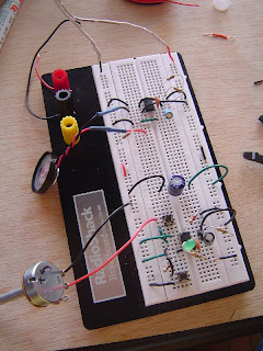
I'm uploading a few closeup shots here of my circuit as I've assembled it. Ignore the color of the red and black wires I'm using to connect the top of my breadboard to the lower part. I haven't yet purchased blue and red Sharpie pens to color code the columns but if you're looking at the photos, the right-most column is positive voltage and the left-most column is negative voltage. I've also used wires to mimic the setup you see in Figure 4-34 so I can have a positive column running down the 2nd from the left side and a negative column running 2nd from the right.
I've also used my multimeter to check the 9V on the 100 microfarad capacitor at the top of my breadboard AND along the bottom - voltage is consistent across the entire breadboard. I also tested my LED again before rebuilding this circuit and all the segments that should light up are working.
At this point, the circuit is still not working. I substituted a 2nd 4026 chip and no luck. According to ACK Supply where I purchased these chips, they are Thomson Consumer Electronics chips - part # "CD4026BE RCA" - I wasn't able to find a data sheet on this particular chip with the Thomson name, but I did find this one from Texas Instruments. I'm assuming here (maybe incorrectly) that all 4026 chips are supposed to have an identical pin layout... but since I can't find one specific to Thomson chips, this may very well be my problem... but I'm guessing that it wouldn't make sense for different chip makers to switch around the pins. Again, maybe I'm wrong.
If you see a wiring problem, let me know... I used black wires to connect the 4026 chip to the negative voltage and red wires for positive. Green wires are used to connect all the other pins to the LED with the exception of pin 9 where I used a black jumper wire. I'm really hoping this is user error and that I'm just being blind to something really really simple... otherwise, I'm going to have to go and purchase additional chips from a different maker just to rule out bad chips or bad pin layouts.
For right now, I'm stuck...
Wednesday, February 17, 2010
Chapter 4 - Exercise 18
I was hoping to have more to post today but I'm a little frustrated with this exercise. I was able to test the three numeral LED (see video below) but after wiring up the very first 4026 chip, I got no response on the LED. I double and triple checked all my wiring using Figure 4-35. I made sure the pins that went to negative voltage went to negative... and the pins that wired to positive voltage were wired to positive.
I checked my pushbutton with an LED - I had it wired correctly.
I checked the 9V voltage... all columns were registering the 9 volts and I properly wired up the columns as seen in Figure 4-34.
So, I grounded myself (again) by touching my metal table... pulled out another 4026... wired it up and pushed the button. Nothing.
Ditto with a 3rd 4026 chip. At this point, I went back to my wiring. The notch on the chip is pointed up (away from the LED) so that would mean pin 1 is upper-left. I again verified all my pins were wired up but nothing. Either this 4026 series of chips I bought isn't working with 9V (and I bumped it to 12V but still no response) or I'm doing something seriously wrong.
I spent over an hour wiring and rewiring just a single 4026 chip... I've got to take a break from this and come back after I've not thought about 4026 chips for a while.
Anyone else have luck wiring this up using Figure 4-35? I just find it hard to believe that these 4026s can be that sensitive... I may have to go buy more before I can finish this exercise... but I'm hoping someone has a suggestion because I'm flat out of ideas.
Tuesday, February 16, 2010
Contest #2 Winners
Back on January 31st, I asked readers to writeup a small comment about their experiences with the book, good or bad. Out of the 6 valid responses, I picked two names at random: Mike and Skain.
I need Mike and Skain to email me so I can tell them how to get their Maker's Notebooks. Thanks to all of you for your comments which I hope Charles Platt and MakerSHED find useful.
Chapter 4 - Exercise 17
For Exercise 16 I built the circuit towards the bottom of the breadboard... if I had read ahead, I would have seen that Exercise 17 was built towards the bottom. Oh, well... in my pictures, the LED circuit (Ex16) is at the bottom and the speaker circuit (Ex17) is at the top.
For the exercise, I (once again) lacked a .047 microfarad capacitor. But luckily, this circuit is all about flexibility. R1 and C1 are the controlling components that will allow us to modify the sound emitted by the speaker... so, on page 166 I noticed that the author included a few capacitors in there that I did have - namely 4.7 microfarad and 47 microfarad. The chart indicates that I should get some sort of sound from the speaker... so let's see.
First, I installed the circuit in Figure 4-21 using a value of 4.7 microfarads for C1. All other components were as listed. Because I'd already wired up C3 in Exercise 16, there was no need to do that again. Remember, C3 is for smoothing the voltage provided by the 9V power supply and the author recommends always including this for integrated circuits.
The first video below will show you that my speaker is emitting a low but fast sound... and the LED circuit is still working.
Next, I removed the 4.7 microfarad (C1) and replaced it with a 47 microfarad. The second video shows the results of that exercise. As you can hear, the sound is much slower and lower... almost like a fast ticking of a grandfather clock. (That loud clicking sound you often hear in my videos is a foot pedal power switch I have installed... I leave the foot pedal plugged into the wall and plug in my adapter to the pedal... I press the pedal with my foot to turn on and off the power.)
Finally, I shorted the power (pin 8) for the speaker circuit to the output (pin 3) of the LED circuit using the long red wire seen in the photograph. I turn on the power (with my foot pedal, but not heard in the 3rd video) and the speaker will not emit any sound until I press the button on the LED circuit... notice also that the reset (pin 4) button immediately kills the sound coming from the speaker.
There is a LOT of information in Exercise 17... I plan on re-reading it once or twice... I may even go back and read Exercise 16 and 17 together... I think we all need a solid understanding of what's going on here - especially the descriptions provided on pages 158 and 164 where the timer chip is explained with a little more detail. What's working for me now is I'm totally understanding how all the components in these circuits are working together to give me the expected results... I understand WHY that capacitor is where it is... WHY that resistor is necessary... WHY that second capacitor is there and WHAT it's used for...
Also, don't skip the last sections on chaining chips together... I had to read it a few times to sink in and I still need some time to process it all. I think knowing that it's hard to damage the 555 timer once it's installed in the circuit makes it easier to play around with the various components. Be sure to work through some of the modifications mentioned on pages 168-169.
Finally, if anyone tackles Figure 4-29, please let me know. I may try it this weekend when I have some extra time, but I really don't want to slow down on the book and this one looks tricky to implement. I have 10 of the 555 chips, so I've got enough to give it a shot, but if anyone has tried it or plans to do so, let me know.
Monday, February 15, 2010
Recovering from The Crud...
Sorry I've been away for a bit... haven't forgotten about the book... just been sick with something that took me out for a few days and then came back with a vengeance. I think I'm finally on the mend, so I'm going to try and get Exercise 17 completed today and hopefully have it written up and posted tonight or tomorrow...
Thursday, February 11, 2010
The Mouser Encyclopedia
I just checked my mail... crammed into the mailbox was this 2190 page catalog. I'm guessing that if it is an electronics component and someone makes it... it's probably in here.
And what really strikes me as funny is that this is the February to July 2010 catalog... so I'm guessing I'll be getting another one of these in July or August... I'd really prefer not to, so I'll probably call them and ask them to take me off the list. I can't imagine the catalog changing all that much (except maybe for subtle price changes). The little bit of environmentalist in me figures I'd rather save the 2 or 3 trees it takes to print this thing... just a thought for those of you placing orders with Mouser.
Chapter 4 - Shopping List
I gathered the Chapter 4 components and tools from a variety of sources.
Below, I've included description, part #, price, and where purchased.
Looking online, I paid way more than I should have for the various chips, but I was able to obtain them locally and visually inspect them. I also got a 20 minute education in other chips, so I figure the extra I spent was worth the extra information... future chip purchases, however, will likely come from Mouser.com where I think I see the best prices... please feel free to chime in about what you've found in terms of prices.
Components
ACK Supply for all chips below:
555 Timer chips x10, CA555E RCA, $0.80 each
$1.59 each for
CD74HC00E RCA
CD74HC02E RCA
CD74HX04E RCA
CD74HC08E RCA
CD74HC32E RCA
CD74HX86E RCA
CD4026BE RCA, $2.59 each
7492, $2.05 each
7406, $1.67 each
74LS27, $1.59 each
-----
Radio Shack Online items below
Item: 2761995
Description: 8-Pin Retention Contact
Quantity: 5 @ $.48
Item: 2761999
Description: 14-Pin Retention Contact
Quantity: 5 @ $.99
Item: 2761998
Description: 16-Pin Retention Contact
Quantity: 5 @ $.99
-----
AllElectronics.com items below
12-key numeric keypad - KP-12 (12 BUTTON KEYPAD - (KP-12)) $4.95
-----
Mouser.com components below
638-HLMPK150 Red LED, 660nm, $0.18 each
604-BC56-11EWA,HI EFF RED DIFFUSED numeric display, $2.73 each
Latching Relay 769-DS2E-SL2-DC5V 2A 5VDC DPDT, $4.86 each
10K Trimmer 652-3266Z-1-103LF 1/4" 10Kohms 10% $2.94 each
Voltage Regulator 512-LM7805CT 1A Pos Vol Reg , $0.37 each
Tactile Switches (already purchased for earlier chapter)
-----
Radio Shack Store components below
100K Potentiometer, 271-092 $2.99 each
10K Potentiometer, 271-1715 $2.99 each
5K Potentiometer (already purchased for earlier chapter)
Chapter 4 - Exercise 16
Chapter 4! Finally getting into integrated circuits which have always interested me but I've never quite found a good explanation for how to use them or how they work... until now. That said, I did have to read over this first material about 3 times before it really sunk in. But it's now "sunk."
This exercise is all about the 555 Timer chip. My initial thoughts before reading this chapter was that this was a timer that would keep time... right? Like a stopwatch. Wrong... sort of. I guess it can be used that way in certain circuits, but it's really about holding a pulse (current, I think) for a certain amount of time... an interval that we have control of, by the way. By changing the values of different components, we can manipulate a pulse emitted (allowed?) by the chip to last a specified time (with slight variations).
My photos here show the circuit I built using the schematic on page 155 (Figure 4-15). I tried my hand at building the circuit by only reading the circuit and not looking at Figure 4-16 for help. I got it right the very first time... I was happy about that.
A few differences, though - I lacked a 100 microfarad (C3) capacitor so I substituted a 220 microfarad... since this is for voltage smoothing, I was guessing that as long as it was a minimum of 100mf that I'd be okay... wasn't 100% certain, but willing to experiment. The rest of the components I had in my kit... be sure to note that the voltage has been switched on the breadboard to 9V and the sides are changed - positive voltage on right side, negative voltage on left side. I also had to go back and refresh my memory about the symbol for an LED because I couldn't remember if the long wire was where the arrow was pointing to or away from ("away" is the answer).
Also, be VERY careful with the orientation of your electrolytic capacitors and make certain their positive and negative terminals are inserted into the breadboard properly. Luckily I checked over my components before applying power and discovered I'd reversed C4. I also soldered two lead wires to my potentiometer to make it easier to insert into the breadboard and avoid using patch wires.
Below are three videos - for the one with R4 equal to 100K, the LED stays lit for about 5-6 seconds... difficult to measure it accurately at this point. I next more than doubled R4 to 220K and, as expected, the LED stays lit for well over 10 seconds. Finally, I cut R4 in half and substituted a 51K resistor and the LED stays lit for around 3 seconds. I wanted to mess around with different capacitor values, but my capacitor selection is limited and they are also not as easily doubled and halved in values like resistors.
It does bring up a question which I don't think I've seen covered in the book yet - can you add capacitors like resistors? If I add two 47mf capacitors in series, will it behave as a 94mf capacitor (close to 100mf)? I may play around with this but am not certain if I'll be risking my components... just not sure if this is safe or not. And I don't have enough capacitors to play around with right now, so I'll likely pick up a mixed bag some time this weekend.
I enjoyed this chapter - I'll likely go back and read over this material one more time before starting Exercise 17... not all the pins on the 555 chip have been covered in detail so I'm still fuzzy on some of their uses, but I definitely understand how pins 2, 3, and 4 work and I'm getting better at pins 6 and 7...
Tuesday, February 9, 2010
Chapter 3 - Exercise 15 Completed
A short post and summary today - I've got myself a cold and am not feeling so well.
I got the project box completed - soldered up all the LEDs, button, switches, speaker, etc. I left the power jack on the bottom unfinished... since I don't have a 12V power supply to spare, I'm not sure if I'll complete that part of the project any time soon.
A few notes about the project box - I had to redrill the four holes in the circuit board to mount them to the box - I used a 1/8" bit to enlarge the holes and I purchased 4 #6 bolts to fit in the four holes I drilled in the back of the box. I bought 4 small nylon nuts (#8s) to serve as little posts for the circuit board to sit on... works fine.
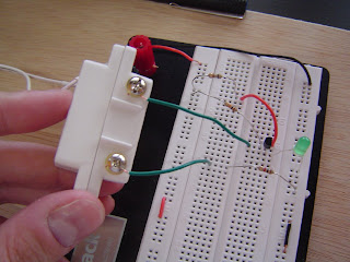
The project works... sort of. The green LED does not light up to test the circuit - either I burned it out (I did use a copper clip) or soldered something incorrectly, but I just can't get that part of the circuit to work. The box does work, however. When I have the magnetic switch closed (see video), I can flip the power switch - the red LED lights up. When I break the magnetic switch, off goes the alarm.
I'm ready to move forward (once I get to feeling better) and away from the exercise, so I'm going to put this aside for now and maybe come back to it in the future to try and figure it out. For now, I've learned what I can from this exercise and am looking forward to Chapter 4 that starts us on Integrated Circuits... woo hoo!
Monday, February 8, 2010
Chapter 3 - Exercise 15 Part 6
Today I worked on the project box. I didn't have the DPDT pushbutton recommended for the project so I substituted a DPDT switch as seen in the pictures. Unlike the pushbutton, I'll have to switch it off manually to stop testing the circuit.
Just an FYI:
* *For the LED holes I used a 3/16" bit
* For the speaker connectors (on bottom of faceplate) I used a 1/8" bit
* For the speaker holes I used a 1/8" bit
for the power jack I used a 11/64 bit"
* For toggle switch (power) I used a 3/8"
* For test DPDT switch I used a 5/8"
Measure your own components, though - I can't guarantee your components will be the exact same size.
For the speaker hole layout, I just used a graphics program to create it and printed it actual size (2" diameter speaker). If you want to use mine, feel free to grab it here. (I'm using MediaFire.com and am not sure how long this file will be available.)
I cut out the printout, taped it to the back of the faceplate and then used a drill bit and hammer to make small dimples in the center of each circle... helps later when you drill them.
As you can see, my project box is almost done... I need to solder it up and make all the various connections. Almost done!
Sunday, February 7, 2010
Chapter 3 - Exercise 15 Part 5
I am smiling ear to ear today... my confidence in soldering just doubled as I was able to move the circuit from the breadboard to the perfboard, little by little, and get it working. For me, one of the keys I feel to my success so far was getting it working on the breadboard first... troubleshooting various issues - wrong resistors, bad transistor, etc - and testing every step of the way.
Last night I successfully moved over the top half of the circuit to the perfboard. As I mentioned in the last post, I soldered each component and then attempted to test my soldering when possible... I used the multimeter to make sure the resistance values were accurate (use the holes in the perf board, not the resistor leads). I also tested voltage across the capacitors to make sure those were soldered properly, too. I haven't yet found (or heard of) a method for testing the 2N2222 and PUTs once soldered, but maybe someone knows a way?
Today I went and purchased a few extra capacitors of various capacitance but was unable to find the 2.2 microfarad capacitors with both leads on one end (shaped like a barrel) - I could only find non-polarized 2.2s with one lead on each end... argh. So, I decided to substitute a 4.7 microfarad for C1 (just like I did for C3)... took a chance because I didn't know how it would alter the circuit, but I felt it was a reasonable risk given the close values. I got home, soldered in the missing capacitor, and tested the top half of the perfboard consisting of the noise maker - the first video below shows my results.
Next, I started moving over the bottom portion of the circuit - the relay/power section. It had fewer components and was slightly easier to solder because not many of the components are sitting next to one another... the exception being the Diode and R1 and R2. (Note: The R1 and R2 on page 135 is NOT the same R1 and R2 in the circuit on page 91.)
Once again I was a little nervous soldering the 2N2222 because those little leads are so close to one another. And pushing my relay through the perfboard was tricky... the holes were just a little too small and my pushing it felt like I was going to snap the perfboard in half... it did finally go in, but it took a couple of minutes of very careful pushing and widening the holes with a large bore needle.
After the circuit was transplanted to the perfboard, I soldered various strands of wire in place - two green wires that will go to the magnetic switch(es), two black wires (twisted together) that go to the speaker, and a red and black wire (twisted) that will provide power.
My second video shows my testing of the circuit outside of the project box. I used gator clips to hold everything together and crossed my fingers...
All in all, I'm having a blast with this book. The heartbeat LED project (Experiment 14) was fun, but this one is really cementing what I've learned about the way resistors, capacitors, transistors, relays, and diodes are working together. Now I've got to get the project box prepared so I can mount the circuit board and close up the box.
Saturday, February 6, 2010
Chapter 3 - Exercise 15 Part 4
I finally got the alarm circuit working for Exercise 15. There were two problems, one human-error and the other not:
1. The two 470K resistors required by the circuit - I was using 470 ohm resistors... HUGE difference! But after finding and replacing them, the circuit still wasn't responding... I had tested all the connections with the multimeter and the LED was working for some reason, but no sound...
so...
2. I swapped out one of my 2N2222 transistors with a new one... Bam! Alarm started working. Swapped out the replacement with the old one... no alarm. Bad transistor...
So, now that the circuit was working, it was time to start soldering it, piece by piece, to the small perfboard I bought from ACK last week to fit in the project box.
First off, these little perfboards are nice and cheap... BUT... the copper tracings you have to solder to are VERY VERY close together. I was worried about soldering the transistors and PUTs because the three leads are so close together. One of my photos shows a closeup and you can see how each row of 6 holes are connected via the copper and how close they are to the row above and below it. Very easy to short circuit if a little solder bleeds over to another row...
As I soldered each item, especially the resistors, I would use my multimeter to check the joint - it's easy to insert the sharp points of the probes into the small holes and see if the reading gives you the proper resistance... all of my resistors for the top half of the circuit are properly soldered... but I can't say the same for the transistors - close examination with my magnifying glass looks okay, but some of those little blobs of solder are awfully close to one another.
I also couldn't fit my large 2.2 microfarad capacitor into the circuit - the capacitor I had had the leads on opposite ends instead of the same end, making it hard to fit the large capacitor (relatively speaking) in place... I'm going to have to purchase a replacement 2.2 that has both leads on one end so I can fit it on the board... it'll go in the upper-right corner in case you're wondering.
I took my time soldering the top half and will do the same with the bottom half of the circuit - but I'm still nervous about shorting out some of the circuit with my not-so-professional soldering skills... but fingers crossed.
Lastly, I'm including a video of the fully wired up alarm system working on the breadboard - if it doesn't sound like yours, please remember that I substituted a 4.7 microfarad for the 2nd 2.2 microfarad and I'm sure it changes the sound a little bit.
Friday, February 5, 2010
More Make: Electronics blogs
Two more blogs with coverage of the various experiments in the book - if you know of any more, please let me know.
Painless Technology
Domo Domo
Painless Technology
Domo Domo
Chapter 3 - Exercise 15 Part 3
Today I wired up the alarm system portion of the breadboard... once again, I lacked two 2.2 microfarad resistors so I substituted a 4.7 microfarad for C3 (in Figure 2-113). When I wired up this noise maker using that combo, it worked... but probably didn't sound exactly like it should with two 2.2 microfarads...
I also modified the relay circuit to look like the one in Figure 3-95. When I break the magnetic switch, I hear the relay kick in and it locks, too - resetting the magnetic switch doesn't turn it off.
I hooked up the speaker... flipped the power... broke the magnetic switch... and nothing.
Argh.
(Keep in mind that I'd already used my multimeter to test voltage/current settings - there was a charge of almost 12V built up on C1 capacitor... and about 11V on the two wires I used to connect to the speaker... so... faulty speaker?
Instead, I connected an LED in place... and it worked. The LED lit up just fine... but shouldn't it pulse? I rechecked all my wiring and components... everything where it should be and voltage across the LED... enough to light it at least. But not enough to get me any noise from the speaker. So I'm back to testing... probably won't get to it until tomorrow, but I'm anxious to build this device, so I'll do my best to figure it out... suggestions or tips welcome.
Movie of the LED lighting up below...
Thursday, February 4, 2010
Chapter 3 - Exercise 15 - Relays the Same?
I may be wrong here - I hope Charles Platt will set me straight - but I think the relay used in Exercise 15 is slightly different than the one we used back in Chapter 2 Exercise 7.
The drawing for Exercise 7 shows the arm of the relay, when the coil isn't powered, pointing in the direction of the coil. When the coil is powered, the magnetic field it creates pushes the arm away (upward). This caused the 2nd LED to light up in Figure 2-60.
But in Exercise 15 the relay shown there has the arm in the "up" position, away from the coil. When the coil is powered, it pulls the arm towards it.
When I was building my circuit, I was using a relay where the arm was pointing towards the coil when not powered... I had to visually inspect the opened one (Exercise 7) to see this... once I saw that, I was able to properly wire my circuit. If I had to modify the circuit in Figure 3-93, I'd have to show the anode of the diode connected to the right-most pins (the one the arm is shown pointing at in Fig 3-93). I hope this makes sense... if we're to assume we're using the same relay from Exercise 7 here, then the circuit in Figure 3-93 would also need to have the arm pointing towards the coil.
Chapter 3 - Exercise 15 Part 2 - It works!
Okay, it was bugging me all afternoon that the circuit wasn't working - and I had a gut feeling it was my wiring, not any of the components. I was careful to identify the anode side of the diode, too... be careful about that.
Anyway, I kept looking at the circuit and then I saw my mistake. I had added the diode into the circuit but I had never connected the coil pin of the relay to the anode side of the diode... I'd left it connected straight to the emitter of the transistor. I'll have to sketch this out and figure out why that mistake kept the relay from locking, but I'll do that later... for now, I'm just happy to have figured out the error (my wiring). This is just more evidence that I need to go slower when building my circuits and check every connection in addition to checking voltage/current with my multimeter.
So, here's a video of the circuit working as it should... when I pull the magnet away from the reed switch, you'll hear the relay click once... and then no matter how many times I push the magnet back onto the reed switch, the relay will not release... it's locked.
I have to admit - it's always nice to figure out your error on your own. I'm including two close-ups of my working circuit - I'm not sure if I've made the wisest/best use of the breadboard, but hey... it works. Now I can continue with the rest of Exercise 15.
Chapter 3 - Exercise 15
Exercise 15 starts out with a small circuit that uses a break in the circuit to trigger an LED to light up. The 2N2222 transistor is used in this circuit, and it's fairly easy to see how it works. I wired in one of my magnetic switches and, after powering up the circuit, pulling away the magnetic end of the switch causes the LED to light... moving the magnetic end back to the reed switch causes the LED to turn off. One of the videos at the end of this post shows this circuit in action.
Next, I removed the LED and 680 ohm resistor as instructed and replaced them with my 12V relay. The idea here is the same... when the magnetic switch is broken, current is allowed to flow through the transistor and triggers the relay... you can't miss it - it's a definite audible click. Pushing the magnet back to the reed switch causes the current to stop flowing and the relay turns off - another click. I've included another video at the end of this post that shows this happening.
Now, the section on Self-Locking Relays makes sense... I read through it twice and followed the circuits and I completely understand how it works... in theory. But building the circuit is another issue. There's no wiring/breadboard diagram here to reference, so I did my best and one of the photos here shows my completed circuit. The problem is that the circuit isn't working the way it's supposed to... when I pull the magnet away, I hear the relay switch on... but it's supposed to lock - if you look close, you can see that I've applied 12V to the middle set of 3 upper terminals on my relay... corresponding to the small arm that moves inside. Moving the magnet back to the reed switch isn't supposed to turn the relay off... but it does. I've got a final video where you can here the relay opening and closing as I move the magnet back and forth.
So, I'm stumped. For now. I'm sure it's something simple that I've missed, and I have a feeling it's related to the fact that there are matching sets of terminals on the relay and I'm likely not wiring one or more of them up properly. From the schematic on page 132 (Figure 3-91) you can tell that the lower two posts of the relay are supposed to be connected - the one on the left connects to the Emitter of transistor... the one on the right connects to the negative voltage. But shouldn't the middle set of terminals (for the moving arm) have it's right-side terminal also connected to the negative voltage? Look at Figure 3-95 on page 135 and you can see that there's a wire added from the middle set's right terminal to the negative voltage side.
Any ideas? My circuit is upstairs, waiting to be fixed...
UPDATE: I went back to Figure 3-91 and thought I'd found my mistake... there's a connection between the Emitter of the transistor and the ON post of the relay. I cut a small piece of wire and connected the Emitter to that post (on the left side of the relay inserted into the breadboard). Turned on the power and the relay went CRAZY. High pitched whining sound that probably isn't a "good" noise. Removing the magnet made it stop, but putting the magnet towards the reed switch caused it to go noisy again... so I'm still missing something...
UPDATE 2: Okay, I happened to glance over at Figure 3-93 and noticed that diode sitting there in the circuit. Of course, I've only read over the Blocking Bad Voltage section once - need to read it again - but I did seem to recall something in there about feedback... so I went up and added in that diode and the noise stopped! Okay, problem is partially solved. It STILL isn't working quite right - when I pull the magnet away (simulating a door opening) the relay is supposed to lock and not disengage when I put the magnet back (closing the door). But it does... argh.
UPDATE 3: Just a warning - these updates could run into the hundreds. Kidding. I went back and took a look at the relay that I tore open in an earlier chapter. It turns out that my relay is off when the arm is in the "down" position, pointing towards the coil. Easy enough - I rewired it so the top post is connected to the diode's anode side. But the relay still isn't locking as it should... something is missing from this circuit... just can't figure out what.
Subscribe to:
Posts (Atom)